Spur Gear Manufacturer, Supplier & Exporter in India
Spur Gear Manufacturer, Supplier & Exporter for Precision Power Transmission
Engineered for efficiency and durability, our spur gears are the cornerstone of high-performance machinery. We manufacture to your exact specifications.
- High-Efficiency Performance (98-99%)
- Robust, Cost-Effective Design
- Manufactured from Certified Materials
- Precision Ground for Smooth Operation
Manufacturing Capabilities
We custom-manufacture spur gears based on your drawings and technical requirements. While ideal for parallel shafts, applications needing lower noise at high speeds may require our helical gears.
| Module | 1 to 25 Module |
| Diametral Pitch (DP) | 1.5 DP to 48 DP |
| Maximum Diameter | Up to 3000 mm |
| Materials | Alloy Steel (EN Series), Carbon Steel, SS, Cast Iron, Bronze, Nylon |
| Heat Treatment | Carburizing, Nitriding, Induction Hardening, Through Hardening |
| Gear Quality Standard | Precision ground up to DIN 6 / AGMA 12 standards |
Common Industrial Applications
Our precision spur gears are trusted in a wide range of demanding sectors:
- Industrial Gearboxes
- Conveyor Systems
- Automotive Transmissions
- Machine Tools (Lathes, Mills)
- Pumping Equipment
- Robotics & Automation
- Printing Machinery
- Power Tools
Understanding Key Gear Parameters
A quick reference for the essential terms used in gear design. For gears to mesh correctly, their Pitch and Pressure Angle must match. These principles also apply to linear motion systems like a rack and pinion.
| Term | Definition & Use | Formula |
|---|---|---|
| Pitch Diameter | The functional diameter of the gear where meshing occurs. | Teeth / Diametral Pitch |
| Diametral Pitch (DP) | (Imperial) The number of teeth per inch of pitch diameter. | Teeth / Pitch Diameter |
| Module (m) | (Metric) The size of the tooth, ratio of pitch diameter to teeth. | Pitch Dia (mm) / Teeth |
| Pressure Angle | The angle of contact between meshing gear teeth (e.g. 20°). | Standard Value |
| Addendum | Height from pitch circle to the top of the tooth. | 1 / Diametral Pitch |
| Dedendum | Depth from the pitch circle to the root of the tooth. | 1.25 / Diametral Pitch |
| Outside Diameter | The gear's largest diameter, used for clearance checks. | (Teeth + 2) / DP |
| Center Distance | The distance between the centers of two mating gears. | (Pitch Dia A + Pitch Dia B) / 2 |
| Gear Ratio | The ratio of rotational speeds between two gears. | Teeth (Driven) / Teeth (Driver) |
Detailed Terminology Explained
Module (Metric) & Diametral Pitch (DP) (Imperial): These two terms define the size of the gear teeth. In the metric system, Module is used; as the module value increases, the tooth size increases. In the Imperial system, Diametral Pitch (DP) is used; it represents the number of teeth on a gear with a one-inch pitch diameter. A higher DP value means smaller teeth. Mating gears must have the same Module or DP.
Pressure Angle: This is the angle between the line of force acting between meshing teeth and the tangent to their pitch circles. It directly affects the load-carrying capacity and efficiency. The most common standard for both metric and imperial gears is 20°, though 14.5° is also seen in older imperial systems.
Addendum & Dedendum: The Addendum is the radial height of the tooth from the pitch circle to its tip. The Dedendum is the radial depth from the pitch circle to the tooth root. The sum of these two values determines the total tooth height and influences the clearances between gears.
Backlash: An essential parameter not shown in the table, backlash is the small gap between mating gear teeth when they engage. A minimum amount of backlash is necessary to prevent the gears from binding, to allow for thermal expansion, and to ensure lubricant can penetrate the contact zone. We control backlash to precise tolerances based on your application's requirements for precision.
Frequently Asked Questions
The primary advantage is high efficiency and a cost-effective design for parallel shafts. It's robust and produces no axial thrust. For angled shafts, a bevel gear would be required.
It depends on load, speed, and environment. Alloy steels excel in high-load scenarios, while Nylon is for low-noise systems. For high gear ratios, a worm gear drive is often an excellent choice.
We provide comprehensive quality assurance documentation, including Material Test Certificates and Dimensional Inspection Reports. You can read more about our commitment to quality here.
Leading manufacturers, including Shreeji Gears, typically produce a wide range of gears such as spur gears, helical gears, internal gears, sprockets, racks, ratchets, bevel gears, and worm gears, among others, to meet diverse industrial needs.
Common materials for spur gears include various types of steel (alloy steel, carbon steel, stainless steel), brass, aluminum, cast iron, and engineering plastics like nylon or acetal. The optimal material depends on the application's load, speed, environment, and specific performance requirements, often combined with appropriate heat treatments for enhanced durability.
Many custom gear manufacturers are equipped to handle both single-piece orders (one-offs) and large production batches for spur gears. Shreeji Gears offers flexible manufacturing capabilities to accommodate varying order quantities, from prototypes to high-volume production runs.
Spur gears can be manufactured in a wide range of diameters, from very small (e.g., 5 mm) up to very large industrial sizes, often exceeding 1 meter (e.g., up to 1500 mm or 59 inches, as offered by Shreeji Gears), depending on the manufacturer's machinery and capabilities.
Yes, many reputable gear manufacturers, including Shreeji Gears, offer comprehensive gear design support and engineering assistance. This can include concept design, material selection, CAD/CAM services, and optimization to ensure the manufactured gear meets performance and application requirements.
Leading gear manufacturers adhere to international quality standards such as ISO, and often work to specific gear accuracy classifications like AGMA (American Gear Manufacturers Association) or DIN (Deutsches Institut für Normung) tolerances. Precision manufacturing involves rigorous gear measuring, inspection, and checks on profile, lead, and tooth root geometry to ensure high quality.
The lead time for custom spur gear orders varies based on several factors, including the complexity of the design, gear size, material availability, required heat treatments, order quantity, and the manufacturer's current production load. Standard spur gears might have shorter lead times than highly customized or specialized components. It's best to discuss your specific requirements with our team for an accurate estimate.
Yes, spur gears are suitable for both high-speed and high-torque applications when correctly designed and manufactured. This involves selecting the right material, achieving high precision in tooth geometry and surface finish, and applying appropriate heat treatments. However, in such applications, factors like noise, vibration, and backlash become more critical considerations, sometimes leading to the selection of helical gears for quieter, smoother operation at very high speeds.
To get accurate pricing for custom spur gears, you typically need to provide detailed specifications. This includes the gear's size (e.g., module, diametral pitch, outer diameter), number of teeth, face width, material, required hardness or heat treatment, bore size, keyway details, and the required quantity. Providing a technical drawing is always ideal for the fastest and most precise quote. For standard stock gears, pricing might be available more quickly.
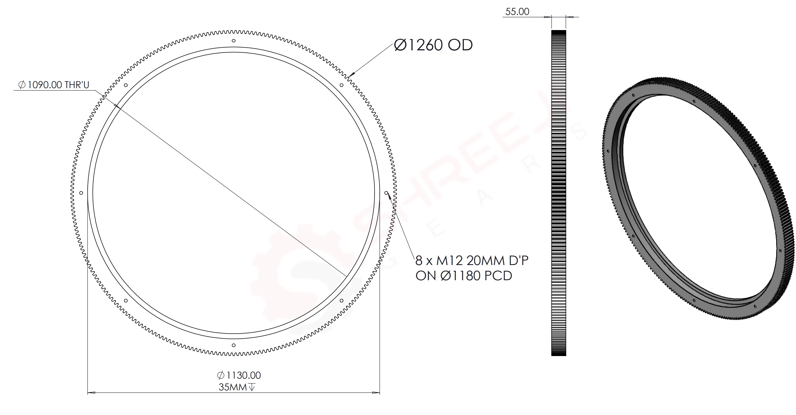
Technical Drawing Example
We manufacture gears from detailed engineering drawings to ensure perfect fit and function.
The Shreeji Gears Advantage
We build more than gears; we engineer reliability for your specific application.
Material & Heat Treatment Mastery
A spur gear's strength lies in its material. We select the optimal alloy (like EN24 for high torque or EN36 for case hardening) and apply precise heat treatments like carburizing or induction hardening to create a gear with a tough core and a wear-resistant surface, ensuring maximum operational life.
Precision for Peak Efficiency
Spur gears are inherently efficient, but only with perfect geometry. Our CNC gear grinding achieves exceptional accuracy (up to AGMA 12), minimizing backlash and operational noise. This precision ensures you get the full 98-99% power transmission efficiency that spur gears are known for.
Your Blueprint-to-Component Partner
We excel at turning your exact technical drawings into functional components. Whether it's a unique bore, a specific keyway, or a non-standard face width, we manufacture to your print, guaranteeing a perfect drop-in fit for your assembly, eliminating integration hassles.
A Deeper Dive into Spur Gear Fundamentals
Understanding the core principles of spur gear design is key to selecting the perfect component for your machinery. As a trusted Spur Gear Manufacturer, Supplier, and Exporter in Ahmedabad, Gujarat, and India, Shreeji Gears delivers precision, durability, and performance in every gear.
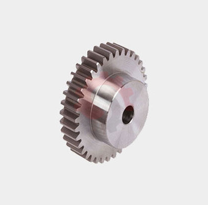
What is a Spur Gear?
A spur gear is the most common type of cylindrical gear. Its defining feature is its straight teeth, cut parallel to the axis of rotation. Simple design and high efficiency make it essential for transmitting power and motion between parallel shafts. Shreeji Gears manufactures spur gears tailored to your precise requirements.
By carefully selecting the size and number of teeth, a spur gear pair can increase torque while decreasing speed, or vice-versa. To mesh correctly, gears must share the same Pitch and Pressure Angle, and the driven gear rotates opposite to the driving gear.
Manufacturing & Materials
We produce spur gears using advanced gear hobbing and shaping machines. Material choice is critical for strength, durability, and noise control. Common materials include:
- High-Strength Steels: Alloy and carbon steels for industrial power transmission.
- Bronze & Brass: For corrosion-resistant applications.
- Plastics & Nylon: For low-load, low-noise environments.
Heat treatment ensures toughness and wear resistance. As a top Spur Gear Manufacturer and Exporter in India, we meet ISO and DIN quality standards.
The Involute Tooth Form
Most industrial spur gears feature an involute tooth profile, which ensures smooth rolling contact and consistent power transmission, even with slight variations in center distance.
Advanced Concept: Profile Shift
Sometimes, gears require a "profile shift coefficient" to avoid undercutting or adjust center distances. Positive shifts strengthen specific designs. Our engineering team applies profile shifts to solve unique challenges. When the coefficient is 0, it’s a standard spur gear. We are a reliable Spur Gear Supplier and Manufacturer in Ahmedabad, Gujarat, and across India.
"The precision and durability of the spur gears from Shreeji Gears have significantly improved the reliability of our conveyor systems. Their team's technical support was outstanding. Highly recommended."— Lead Engineer, Major Automation Firm
Get a Fast, Accurate Quote
Provide us with your technical specifications for a competitive, no-obligation quote.
For the fastest service, please email your technical drawing to support@shreejigears.com. Alternatively, include these key parameters in your inquiry:
- Module or Diametral Pitch (DP)
- OD Outer Diameter
- Number of Teeth & Face Width
- Material & Required Hardness
- Bore Size & Keyway Details
- Required Quantity